An image might depict an individual learning to Circuit Diagram
An image might depict an individual learning to Circuit Diagram Develop your own AI enabled
Dive Deep, Explore More Hudson Vaughn.
The Best Prototyping Tools for 2018 Circuit Diagram Electronic Design Automation (EDA): These tools are
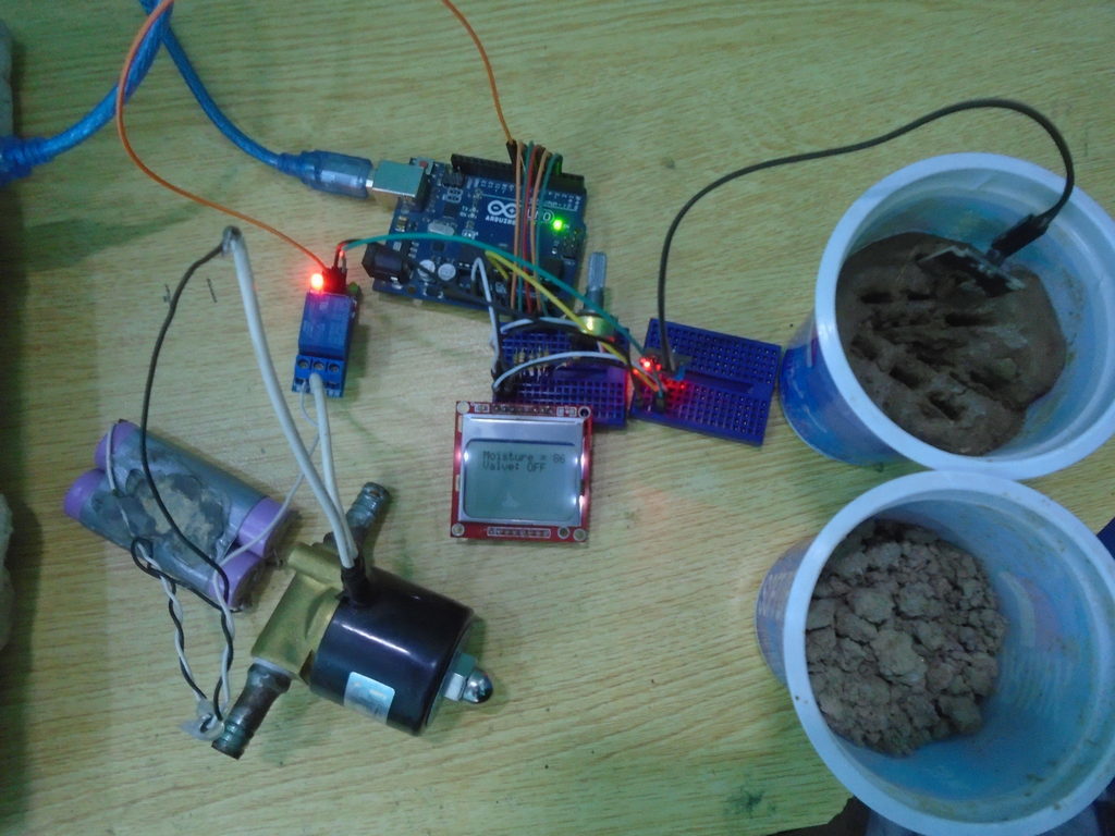
DFRobot Maker Community Circuit Diagram In this DIY project, we will try to make a
IoT based efficient solar panel monitoring Circuit Diagram In this project, we will be making
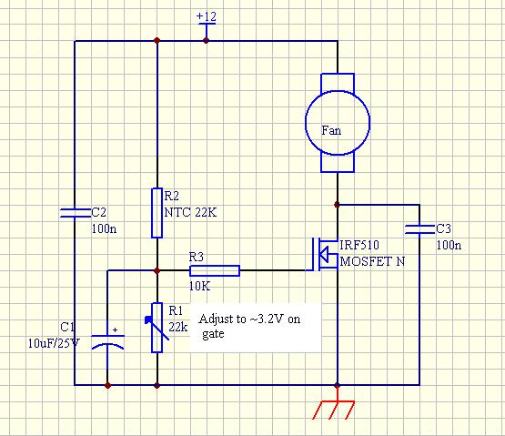
untitled wwwsupercontrolde Circuit Diagram The analysis controller performance in terms of automatic temperature control based
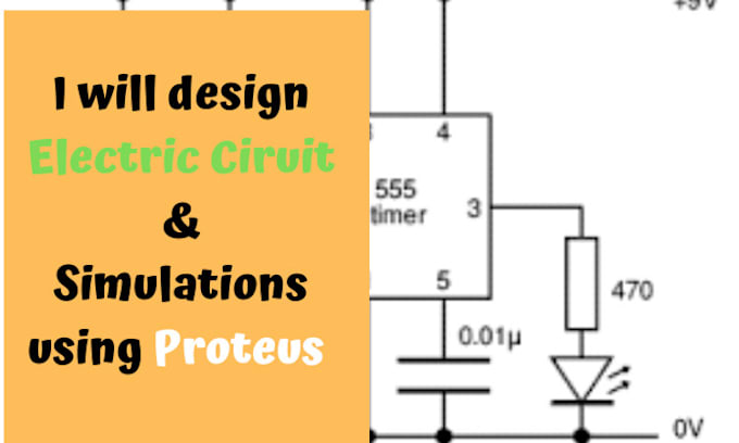
Design electric circuits and simulations in proteus by Engr92246 Circuit Diagram Circuit Simulation using Proteus
IOT Weather Station with NodeMCU OLED OpenWeatherMap Circuit Diagram Step 4: Building a Stevenson Screen
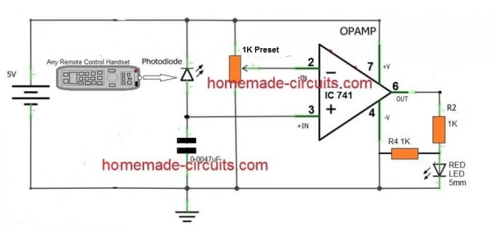
tv remote control circuit diagram The BC557 offers similar characteristics to the BC547, making them
DIY Thermal Camera Build your Own Infrared Imaging Device with ESP32 Circuit Diagram Make Basic
Voltage Multiplier Circuit Diagram Voltage Multiplier Circuits are devices that are designed to generate an
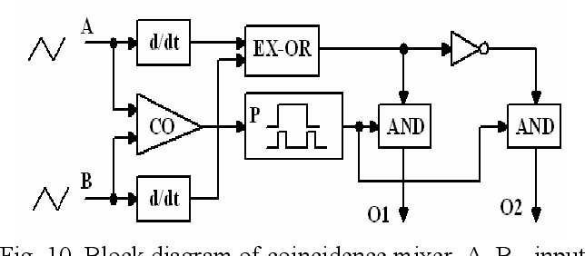
Figure 1 from A FREQUENCY SYNTHESIZER WITH COINCIDENCE Circuit Diagram The Fig. 2.130 shows the
Arduino Circuitos impresos Circuit Diagram After this, you need to create a new instance of
High Low Speed Circuit Circuit Diagram RAYMING⢠has offered high-quality PCBs and the best PCB
7 Best PCB Design Courses For Beginners in 2023 Circuit Diagram This course covers all
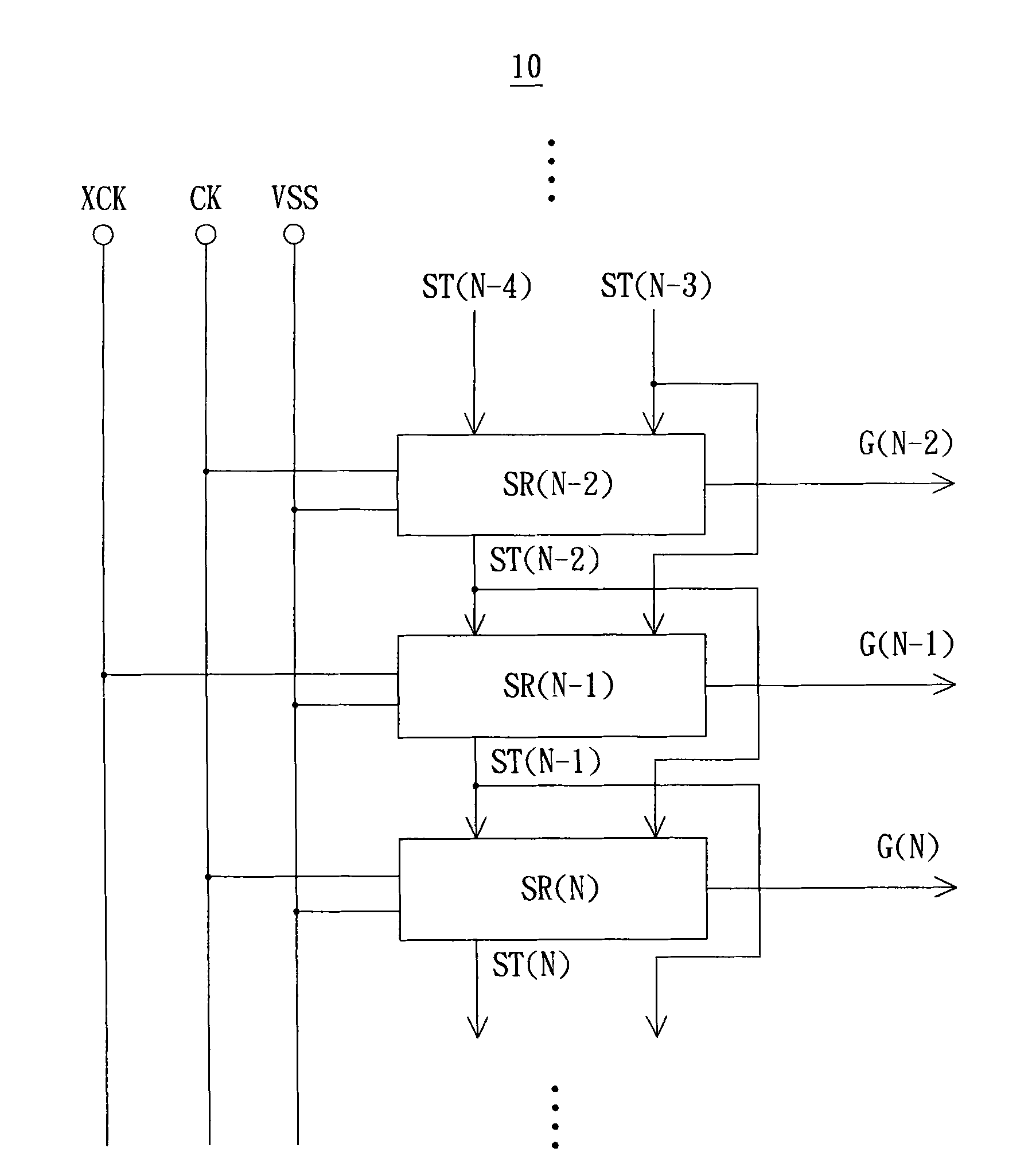
Shift register circuit and shift register Eureka Circuit Diagram The shift register, which allows serial
Electronic Voting Machine for Election Graphic by K for Kreative Circuit Diagram When we press
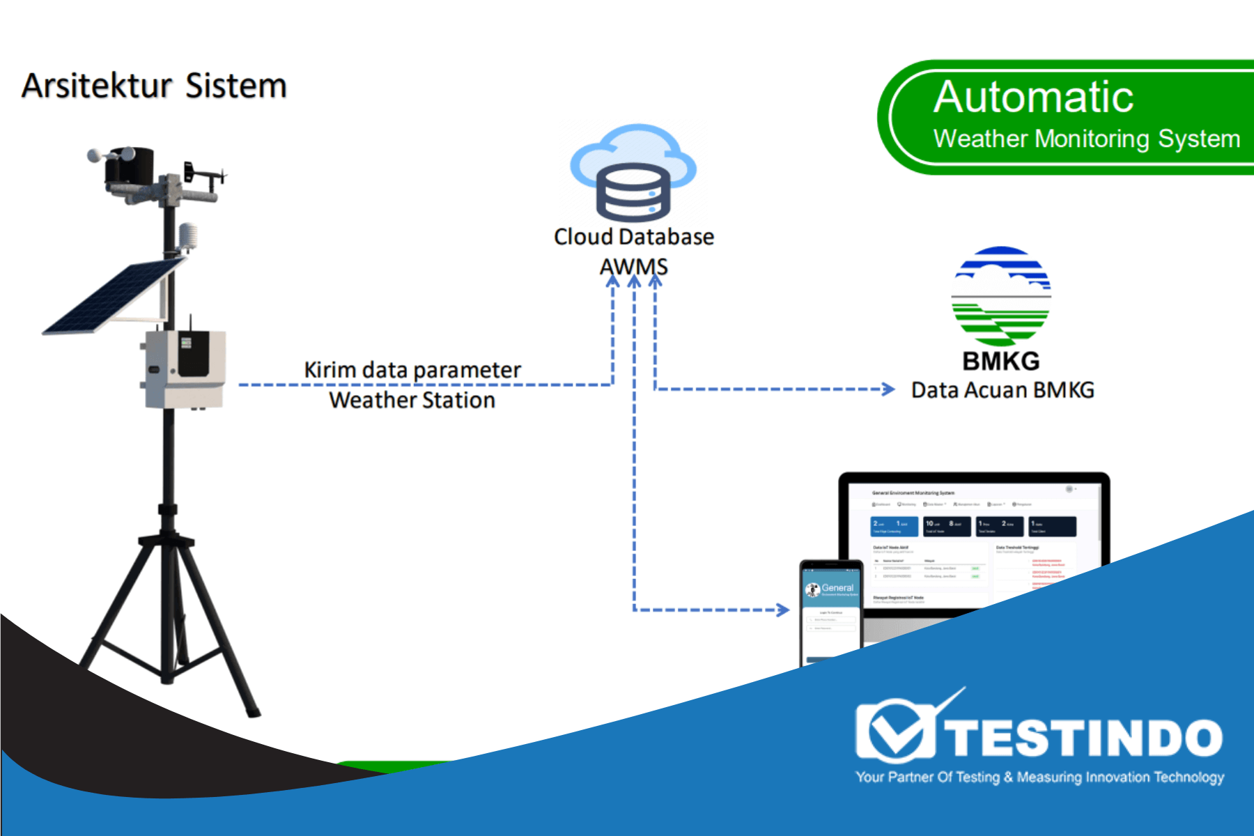
Stasiun Cuaca Otomatis Automatic Weather Station Circuit Diagram The purpose of a wireless weather monitoring
PDF Bluetooth based home automation system using cell phone Circuit Diagram In this project, we
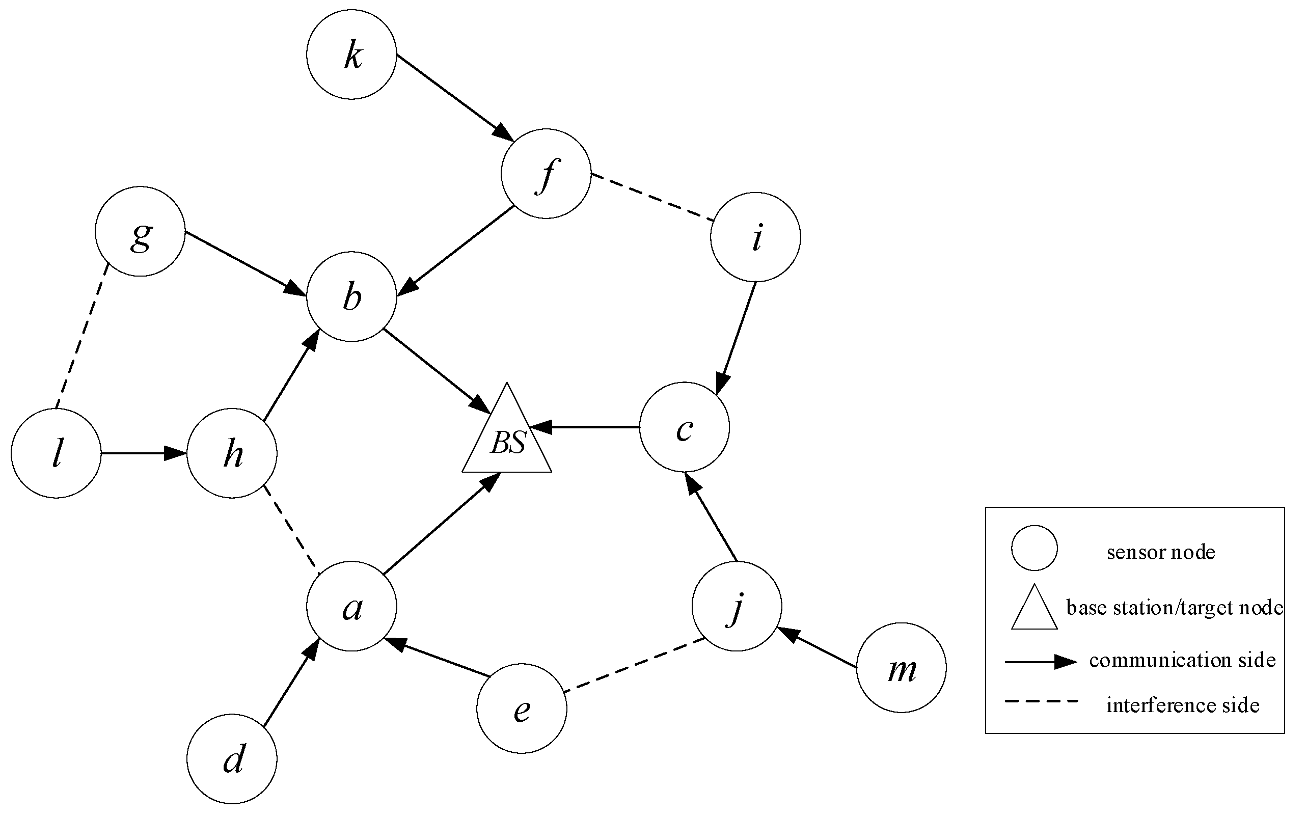
RealTime Data Transmission Scheduling Circuit Diagram Then, input benchmark_tx python file with proper parameters setting
Speed sensor Circuit Diagram We will be using the Hall effect sensor and a magnet
Radio Frequency Generator Circuit Diagram The bridge circuit is C1 R4a and C3 R4b. R4